I designed a wireless dimmer for my smart bulb
The problem

I had this old Yeelight lamp that I've been using for a while. It's a handy device that is useful in many ways.
The biggest issue though, was having to use the app every time I wanted to control it. If I switch it off from my regular switch, it's powered off and I can't control it remotely anymore. Which became frustrating very quick. I know, I could buy a smart switch and get it over with, but these things were expensive, and most importantly, I wanted to solve my issue in my (cooler) way.
When I first had this problem, I was an avid user of the famous Android app "Tasker". I was automating everything with it. So, in the same fashion, I quickly wrote a script that toggles the light whenever I shook my phone. I made sure that it worked as intended and didn't have any false triggers. It served me well until the day my phone got bricked. Suddenly, I had to find another solution.
This was around the time that I was getting comfortable with Fusion 360 and 3D printing. I saw this as a great challenge so, I decided to create the product from scratch, by doing both the design and the software.
Planning
When I started planning, I had these ideas in my mind.
- It has to be smart enough. I didn't want it to be too smart for security purposes. So, no adding more functions that it needs. That's why I eventually called it "dumb".
- It has to be simple to use and maintain.
- It should have the following functions: turning the light on and off, dimming the light, and adjusting the color temperature of it.
- It should look good.
3D Design
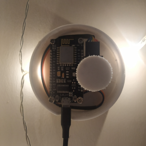
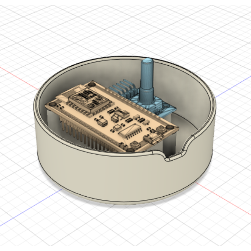
I always liked the transparent-electronics phase of the 90s. I think seeing the components inside of a product gives it a cool appeal. I didn't want to design some closed box. I quickly sketched a little and decided on a design. (I redraw the following sketches for this blog post because I lost my sketchbook from that time.)

Then, I designed it on F360. It was fun. For the knob, I found an open source "openscad" file on a site and adjusted it to my needs.

Software
Writing the software was the easy part. I quickly opened Arduino IDE and started working. I used the "EncoderButton" library for operating the rotary encoder and the "ESP8266WiFi" library to handle wireless communication. Then I had to figure out how I could send commands to the lamp.
I found the document titled "Yeelight WiFi Light Inter Operation Specification" which was very well written and explained how Yeelights operated internally. I got the communication protocol and the commands I should use from there.
Finishing up
I wrote the code and I implemented all the functions I originally planned;
- The user could dim the light or adjust the temperature by rotating the encoder.
- The lamp can be toggled by short-clicking on the encoder.
- The user can switch between dimming-mode to temperature-mode by long-clicking the encoder.
- Essential settings are hardcoded in the firmware and cannot be altered remotely. This ensured the security.
Finally, I 3D printed the case, assembled it, and started 'beta testing' the remote.
Back to brainstorming
I used the remote for a couple of weeks, and I noticed a strange behavior. It was becoming unstable over time. After a short period of debugging, I found the culprit.
In the code, I initially stored the command that would be sent to the lamp using the following array. I picked "40" arbitrarily while I was testing the code and forgot about it.
char buffer[40];
Unfortunately, this 40-character array wasn't enough to hold the more-than-40-char-commands. This caused a buffer overflow every time I used the remote. I quickly fixed it by increasing the size of the buffer.
char buffer[70];
A small redesign
After fixing the bug, I wanted to slightly alter the design. Initially, I wanted to put something transparent in front of the components to protect them and keep everything tidy. However, I couldn't find a workshop that accepted non-bulk orders (we need more makerspaces in Istanbul immediately). This limitation was the reason for the open design. Later on, I made a second version of the design with a thin acrylic panel on the front, just in case I could eventually get it manufactured.

🎉Tada!
When I completed the project, I was really pleased. I had a chance to experience a product development cycle myself while solving a real-life problem. I published my design and the code I wrote on GitHub, so anyone can benefit from the project and contribute if they want.
 |
 |